Support our educational content for free when you purchase through links on our site. Learn more
Industrial Robot Instructions: 10 Rules 🤖


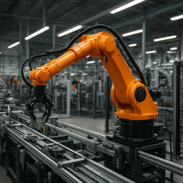
Industrial robot instructions should be built around safe motion, accurate calibration, reliable I/O, and predictable recovery. The best robot program is not merely one that reaches the target; it completes the task repeatedly while protecting people, parts, tooling, and production uptime.
A robot controller may execute thousands of commands per day, but one incorrect tool frame or missing sensor check can turn a routine pick-and-place cycle into a collision investigation. We’ve seen a program look perfect in simulation, then fail on the factory floor because a fixture shifted a few millimeters or a gripper confirmation signal was mapped incorrectly.
That is why effective industrial robot instructions combine motion commands, coordinate systems, PLC handshaking, safety logic, testing, documentation, and maintenance support. The arm is only one member of the team. The tooling, sensors, software, operator, and maintenance technician all get a vote.
Key Takeaways
- Calibrate the TCP, tool frame, work object, and robot mastering before teaching production positions.
- Use the correct manufacturer programming environment, such as ABB RAPID, FANUC TP/KAREL, KUKA KRL, Yaskawa INFORM, or Universal Robots PolyScope and URScript.
- Separate robot motion from process logic so programs remain easier to test, troubleshoot, and modify.
- Add PLC handshaking and sensor confirmation for grippers, fixtures, machine doors, conveyors, and process completion.
- Test progressively, beginning with simulation and reduced-speed single-step operation before full automatic production.
- Design recovery routines deliberately for missing parts, failed grips, sensor timeouts, communication faults, and power interruptions.
- Treat robot safety as a complete-cell responsibility, following applicable guidance such as ISO 10218, ISO/TS 15066, ANSI/RIA R15.06, and OSHA requirements.
- Measure cycle time, repeatability, downtime, quality, and operator intervention to prove that the instructions improve manufacturing performance.
- Back up programs, calibration data, safety configuration, PLC files, and HMI files before making changes.
- Use experienced integration and service support when retrofitting equipment, modifying legacy programs, or troubleshooting uncertain cell behavior.
Table of Contents
- ⚡ Quick Tips and Facts About Industrial Robot Instructions
- 🤖 Industrial Robot Instructions: What They Are and Why They Matter
- Robot Programs, Teach Pendants, and Motion Commands Explained
- Industrial Robot Instructions vs. PLC and CNC Programming
- 🏭 From Factory Automation History to Modern Robot Programming
- The Evolution of Industrial Robot Controllers
- How Collaborative Robots Changed Instruction Design
- 🧭 Industrial Robot Types and Their Instruction Requirements
- Articulated Robot Programming
- SCARA Robot Instructions
- Cartesian and Gantry Robot Commands
- Delta Robot Motion Instructions
- Collaborative Robot Setup and Programming
- 🧰 Essential Components of an Industrial Robot Instruction
- Coordinate Systems, Frames, and Tool Center Points
- Joint, Linear, Circular, and Spline Motion
- Speed, Acceleration, Blending, and Zone Settings
- Digital Inputs, Outputs, and Industrial I/O Signals
- Timers, Counters, Variables, and Registers
- Conditional Logic, Lops, Subroutines, and Interrupts
- 💻 Industrial Robot Programming Languages by Manufacturer
- ABB RAPID Instructions
- FANUC TP and KAREL Programming
- KUKA KRL Robot Commands
- Yaskawa INFORM Programming
- Universal Robots Polyscope and Script
- Stäubli VAL3 Programming
- Epson RC+ and Kawasaki AS Programming
- 📝 How to Write Industrial Robot Instructions Step by Step
- 1. Define the Manufacturing Task and Cycle Requirements
- 2. Select the Robot, End-of-Arm Tooling, and Workcell Layout
- 3. Establish Tool and User Coordinate Frames
- 4. Teach Safe Reference and Approach Positions
- 5. Program Pick, Process, and Place Motions
- 6. Add Sensors, Handshaking, and Fault Recovery
- 7. Test, Simulate, and Optimize the Robot Cycle
- 🎯 Industrial Robot Instructions for Common Applications
- Pick-and-Place Robot Programming
- Machine Tending and CNC Loading
- Welding and Arc-Tracking Instructions
- Palletizing and Depalletizing Programs
- Assembly, Insertion, and Press-Fit Operations
- Painting, Dispensing, and Surface Finishing
- Packaging, Case Packing, and Inspection
- 🛡️ Robot Safety Instructions and Risk Reduction
- Emergency Stops, Safeguarding, and Safety Interlocks
- Manual, Teach, Automatic, and Reduced-Speed Modes
- Lockout/Tagout and Safe Maintenance Procedures
- Industrial Robot Safety Standards: ISO 10218, ANSI/RIA R15.06, and ISO/TS 15066
- ✅ 10 Best Practices for Reliable Robot Programs
- Use Clear Names, Comments, and Program Structure
- Build in Collision Avoidance and Recovery Paths
- Control Cycle Time Without Sacrificing Quality
- Validate Every Assumption at the Workcell
- 🔧 Commissioning, Calibration, and Robot Accuracy
- Mastering, Zeroing, and Encoder Calibration
- Tool Center Point and Payload Verification
- Robot Base Frame and Work Object Calibration
- Offline Programming and Digital Twin Simulation
- Renishaw and Other Robot Calibration Technologies
- 🧪 Testing, Debuging, and Troubleshooting Robot Instructions
- Common Motion, Reach, and Collision Errors
- I/O, Sensor, Gripper, and Fieldbus Faults
- Positioning Accuracy and Repeatability Problems
- Alarm Codes, Program Recovery, and Restart Logic
- How to Debug a Robot Program Without Creating New Problems
- 🔌 PLC, Vision, Conveyor, and MES Integration
- Robot-to-PLC Handshaking
- Machine Vision-Guided Robot Instructions
- Conveyor Tracking and Line Synchronization
- EtherNet/IP, PROFINET, EtherCAT, and DeviceNet Communication
- Traceability, Data Collection, and Manufacturing Execution Systems
- 📊 Measuring Robot Performance and Return on Automation
- Cycle Time, Throughput, Availability, and OEE
- Robot Accuracy, Repeatability, and Process Capability
- Reducing Downtime, Scrap, and Manual Intervention
- 👥 From Concept to Code: Engineering Industrial Robot Success Together
- Application Assessment and Workcell Design
- Controls Engineering, Robot Integration, and Validation
- Tailored Robotics Solutions for Real-World Factory Constraints
- 🤝 Industrial Automation Support Beyond Installation
- Robot Programming, Retrofitting, and Production Ramp-Up
- Preventive Maintenance and Lifecycle Service
- Remote Diagnostics and Online Robot Service Portals
- Support for Existing Robot Cells, Regardless of Installer
- Training Operators, Technicians, and Robot Programmers
- 🌐 Industrial Robot Manufacturers, Integrators, and Resources
- Leading Industrial Robot Brands
- Choosing an Automation Integrator
- Robot Manuals, Programming Guides, and Technical Documentation
- When to Use Manufacturer Support or an Independent Engineer
- 🚀 The Future of Industrial Robot Instructions
- AI-Assisted Robot Programming
- No-Code and Low-Code Robot Interfaces
- Adaptive Automation, Force Control, and Smart Sensors
- Cybersecurity for Connected Robot Controllers
- 🧠 Quick Reference: Industrial Robot Instruction Glossary
- Conclusion
- Recommended Links
- FAQ
- What are industrial robot instructions?
- How do you program an industrial robot?
- What programming language does an industrial robot use?
- Are industrial robot instructions difficult to learn?
- What is the difference between teaching and offline programming?
- How can I make a robot program safer and faster?
- How often should industrial robot programs be backed up?
- Who can troubleshoot or modify industrial robot instructions?
- Reference Links
Quick Tips and Facts About Industrial Robot Instructions
If you want the practical starting point, read our guide to Robot Instructions first, then use this checklist before touching a teach pendant:
- ✅ Define the task before writing motion commands. Specify the part, tooling, reach, payload, cycle time, accuracy, and required production rate.
- ✅ Calibrate the Tool Center Point (TCP), work object, and robot base frame before teaching production positions. A beautifully written program with a bad TCP is still a beautifully written mistake.
- ✅ Use the robot manufacturer’s programming language. ABB uses RAPID, FANUC commonly uses TP and KAREL, KUKA uses KRL, Yaskawa uses INFORM, and Universal Robots uses PolyScope with URScript.
- ✅ Separate motion logic from process logic. Keep robot movement, gripper control, sensors, alarms, and recovery routines organized rather than tossing everything into one giant program.
- ✅ Add handshaking with the PLC. “Robot ready,” “part present,” “clamp closed,” and “cycle complete” signals prevent the robot from guessing. Robots are clever, but guessing is not a safety strategy.
- ✅ Test at reduced speed first. Run single-step, teach, and dry-cycle modes before automatic production.
- ✅ Plan recovery paths. A robot that stops safely but cannot restart cleanly will turn a small sensor fault into a production headache.
- ✅ Use simulation where practical. FANUC ROBOGUIDE and comparable offline programming tools can expose reach, collision, and cycle-time problems before installation.
- ✅ Treat collaborative operation as a risk-assessed application, not a marketing label. Review ISO 10218 and ISO/TS 15066, then validate the complete cell.
- ❌ Never assume a cobot is automatically safe. The end effector, part, pinch points, speed, layout, and surrounding machinery may introduce hazards.
- ✅ Back up programs, calibration data, parameters, and controller images. A production robot without a current backup is a very expensive memory test.
- ✅ Document every change. Include the date, programmer, reason, affected files, and validation result.
- ✅ Measure the result. Cycle time, first-pass yield, downtime, repeatability, and operator interventions tell you whether the instructions actually improved the process.
Fast robot-selection guide
| Production requirement | Usually worth considering | Why |
|---|---|---|
| Heavy lifting and complex access | Six-axis articulated robot | Flexible wrist orientation and broad work envelope |
| High-speed small-part assembly | SCARA robot | Fast planar motion and strong repeatability |
| Rapid pick-and-place | Delta robot | Excellent speed for lightweight products |
| Large rectangular work area | Cartesian or gantry robot | Straightforward X/Y/Z motion and scalable travel |
| Human-adjacent, flexible tasks | Collaborative robot | Easier redeployment and guided teaching, subject to risk assessment |
| Wet or hygienic production | Food-grade or washdown model | Better environmental suitability and cleanability |
One question will keep appearing throughout this guide: is the hardest part writing the instruction, or proving that the instruction behaves correctly in the real cell? We have found the second part usually wins.
Industrial Robot Instructions: What They Are and Why They Matter
Industrial robot instructions are the commands, parameters, logic, and signals that tell a robot controller how to perform a manufacturing task. They define where the robot moves, how fast it travels, what it does with its tool, how it communicates with machines, and what happens when something goes wrong.
A useful robot program may include:
- Motion commands
- Tool and coordinate-frame data
- Speed, acceleration, and blending settings
- Digital input and output instructions
- Conditional logic
- Timers, counters, and variables
- Fault handling and recovery
- Safety-related interlocks
- Communication with PLCs, vision systems, conveyors, and MES software
The Occupational Safety and Health Administration describes robot hazards around factors such as unexpected startup, reaching into the work envelope, and improper maintenance. That is why robot instructions cannot be treated like ordinary software alone. They are software attached to moving steel, sharp tooling, heat, pressure, electricity, and production deadlines.
Robot programs, teach pendants, and motion commands explained
Most industrial robots are programmed through a teach pendant, a handheld controller with a display, jog keys, mode controls, and programming functions. Some systems also support:
- Offline programming software
- Graphical block programming
- Direct hand-guiding
- Text-based programming
- Vision-guided position generation
- PLC-driven task selection
- API or network-based control
A simple pick-and-place sequence might look like this:
Move to safe home position
Wait for part-present signal
Move above pickup point
Move linearly to pickup point
Close gripper
Confirm gripper-closed signal
Move vertically away from fixture
Move to place approach point
Move linearly to place point
Open gripper
Confirm part-released signal
Return to safe position
Report cycle complete
``

The syntax varies by brand, but the logic is remarkably consistent. A FANUC TP program, ABB RAPID routine, KUKA KRL program, and Yaskawa INFORM job may look different on screen, yet each still needs **safe approach, controlled grasp, confirmation, placement, and recovery**.

### Industrial robot instructions vs. PLC and CNC programming

Robot programming overlaps with PLC and CNC programming, but the mental models differ.

| System | Primary job | Typical instruction focus | Common failure |
|---|---|---|---|
| Industrial robot controller | Move a robot and operate a tool | Position, orientation, path, payload, I/O | Collision, wrong frame, unreachable point |
| PLC | Coordinate machines and safety-related sequences | Logic, interlocks, timers, state machines | Incorrect handshake or sequence state |
| CNC controller | Move cutting tools through programmed paths | Toolpaths, spindle speed, feeds, offsets | Tool crash, incorrect work offset |
| Vision controller | Locate, inspect, or classify parts | Image acquisition, calibration, results | Bad lighting, false detection |
| MES or SCADA | Track production and equipment data | Recipes, traceability, status, reporting | Data mismatch or communication loss |

The robot should not independently decide that a fixture is clamped simply because a timer expired. The PLC should provide a validated signal. Likewise, a PLC should not assume that a robot reached a position merely because it issued a start command. **Every critical action needs confirmation.**

## From Factory Automation History to Modern Robot Programming

Industrial robot instructions evolved from relatively simple point-to-point jobs into coordinated systems involving vision, force sensing, digital twins, safety scanners, and cloud-connected diagnostics.

The first production robots were valued for repeatable handling and welding. Modern cells may ask a robot to:

- Identify randomly oriented parts
- Adjust its path based on vision
- Track a moving conveyor
- Apply force during insertion
- Exchange tools automatically
- Report quality data
- Recover from a partial failure
- Coordinate with multiple robots and machines

The robot has not become “smart” by magic. The instruction architecture has become richer.

The [International Federation of Robotics](https://ifr.org/industrial-robots) tracks industrial robot adoption and describes industrial robots as automatically controlled, reprogrammable, multipurpose manipulators programmable in three or more axes. That definition matters because **reprogrammability** is central: the same hardware can weld one product today and tend a machine tomorrow, provided the tooling, safety design, and instructions support the change.

### The evolution of industrial robot controllers

| Era | Programming style | Typical capability | Engineering trade-off |
|---|---|---|---|
| Early production automation | Hardwired or simple point teaching | Repetitive transfer and welding | Reliable but inflexible |
| Teach-pendant era | Recorded positions and basic logic | Repeatable production sequences | Easier to deploy, harder to maintain at scale |
| Structured programming era | Variables, subroutines, registers, conditional logic | Flexible recipes and diagnostics | Requires stronger programming discipline |
| Networked-cell era | PLC, fieldbus, vision, and HMI integration | Coordinated automation | More capability, more interfaces to troubleshoot |
| Simulation and digital-twin era | Offline programming and virtual commissioning | Collision checking and process validation | Better planning, but models must match reality |
| Adaptive and connected era | Vision, force control, analytics, AI assistance | Variable production and condition-based response | Greater complexity and cybersecurity exposure |

### How collaborative robots changed instruction design

Collaborative robots from brands such as [FANUC](https://www.fanucamerica.com/products/robots/collaborative-robots), [Universal Robots](https://www.universal-robots.com/products/), [ABB](https://www.abb.com/global/en/areas/robotics/products/robots/collaborative-robots), and [Dosan Robotics](https://www.dosanrobotics.com/en) made guided teaching and rapid redeployment more accessible.

A collaborative robot may let an operator:

- Move the arm by hand
- Record waypoints
- Adjust speed through a graphical interface
- Configure gripper actions with function blocks
- Reuse task templates
- Change production recipes without rewriting every low-level instruction

That convenience is valuable, but it can hide complexity. A hand-guided path still needs:

- Correct TCP data
- Correct payload settings
- Collision and pinch-point review
- Safe tool behavior
- Proper restart logic
- Validation under actual production conditions

Our engineers have seen a familiar pattern: the first demonstration works beautifully, then the robot encounters a slightly shifted part, a reflective surface, or a full bin. The “easy” program becomes a systems-enginering problem. That is where disciplined instructions matter.

## Industrial Robot Types and Their Instruction Requirements

Robot geometry strongly influences instruction design. The first featured video, [#featured-video](#featured-video), presents the main industrial robot families and their applications, including articulated, SCARA, Cartesian, cylindrical, spherical, and parallel or delta robots.

### Articulated robot programming

Articulated robots use rotary joints, commonly four, five, or six axes. Brands such as [FANUC](https://www.fanucamerica.com/products/robots), [KUKA](https://www.kuka.com/en-us/products/robotics-systems/industrial-robots), [ABB](https://www.abb.com/global/en/areas/robotics), and [Yaskawa Motoman](https://www.yaskawa.com/products/robotics/industrial-robots) offer extensive articulated portfolios.

They are well suited to:

- Arc and spot welding
- Machine tending
- Paletizing
- Assembly
- Painting
- Dispensing
- Material handling
- Cutting and material removal

Instruction priorities include:

- Wrist orientation
- Elbow configuration
- Singularities
- Joint limits
- Collision avoidance
- Payload and inertia
- External axes
- Tool orientation along a path

A position that is reachable in Cartesian space may still be awkward or unsafe in joint space. Two robot configurations can place the TCP at the same coordinates while the arm takes very different postures. This is why experienced programmers inspect the robot’s full posture, not just the tool tip.

### SCARA robot instructions

SCARA means **Selective Compliance Assembly Robot Arm**. These robots typically excel at fast horizontal movement, vertical insertion, assembly, dispensing, and packaging.

Instruction priorities include:

- High-speed point-to-point movement
- Controlled Z-axis insertion
- Accurate rotation
- Part-present confirmation
- Press-fit or insertion force management
- Short, clean motion paths

A SCARA is not simply a “small articulated robot.” Its mechanical behavior and work envelope are different. Programming an insertion task often requires a carefully controlled vertical approach, a slower final move, and a sensor or force confirmation.

### Cartesian and gantry robot commands

Cartesian robots move along linear X, Y, and Z axes. Gantry systems are especially useful for large work areas, palletizing, machining support, dispensing, and material handling.

Benefits include:

- Predictable rectangular work envelopes
- Straightforward coordinate interpretation
- Easy scaling for long travel
- Strong payload potential
- Clear relationship between axis movement and location

Drawbacks include:

- Larger structural footprint
- More exposed linear components
- Potential cable-management challenges
- Less wrist flexibility than a six-axis arm

Cartesian instructions are often easier to visualize, but that does not eliminate safety hazards. A large gantry can sweep an enormous area, and its linear motion may be deceptively fast.

### Delta robot motion instructions

Delta robots use parallel linkages and are designed for high-speed pick-and-place, sorting, packing, and lightweight assembly. [FANUC’s delta robot range](https://www.fanucamerica.com/products/series/m-3) illustrates how these systems target speed and repeatable product transfer.

Instruction priorities include:

- Conveyor tracking
- Vision-generated pick points
- Fast approach and retreat paths
- Product orientation
- Gripper timing
- High-speed I/O
- Consistent product presentation

A delta robot can be spectacularly fast, but its performance depends heavily on the surrounding system. Poor product spacing, inconsistent vision results, or a sluggish gripper can erase the advantage of a fast arm.

### Collaborative robot setup and programming

Cobots are commonly used for:

- Light assembly
- Machine tending
- Packaging
- Inspection
- Screwdriving
- Gluing and dispensing
- Paletizing
- Welding with appropriate equipment

The instruction set often emphasizes:

- Simple waypoints
- Reduced-speed operation
- Force or contact limits
- Tool configuration
- Safety planes
- Reduced-mode behavior
- Operator prompts

FANUC’s CRX series emphasizes intuitive teaching, while Universal Robots centers much of its programming experience around PolyScope. These are useful approaches, but **ease of programming is not the same as ease of validating a complete workcell**.

## Essential Components of an Industrial Robot Instruction

A reliable program is not just a list of coordinates. It is a controlled description of **motion, context, timing, communication, and failure behavior**.

### Coordinate systems, frames, and Tool Center Points

Most robot systems use several coordinate concepts:

- **World or base frame:** The robot’s relationship to the cell
- **User frame or work object:** The part, fixture, pallet, or process coordinate system
- **Tool frame:** The orientation and location of the TCP relative to the robot flange
- **Joint coordinates:** Individual axis positions
- **Cartesian coordinates:** X, Y, Z and orientation values

The TCP is especially important. If a gripper finger extends 200 mm beyond the flange but the controller thinks the tool is 50 mm long, every taught position becomes suspect.

A practical calibration sequence is:

1. Mount the tool securely.
2. Enter the approximate tool geometry.
3. Use the controller’s multi-point TCP calibration routine.
4. Approach a fixed reference point from several orientations.
5. Calculate the TCP.
6. Verify the result with independent approach directions.
7. Record the calibration date and method.
8. Recheck after a tool change or collision.

For measurement and calibration technologies, consult [Renishaw’s support page for industrial robot calibration products](https://www.renishaw.com/en/support-for-industrial-robot-calibration-products--48456). The page may require a retry or direct contact when unavailable, so use manufacturer documentation and validated measurement procedures rather than relying on an unverified number.

### Joint, linear, circular, and spline motion

#### Joint motion

Joint or axis-interpolated motion moves each axis toward the target. It is often fast and efficient, but the TCP may follow a curved path.

Use it for:

- Travel between distant points
- Non-process repositioning
- Home and standby movements
- Areas with generous clearance

#### Linear motion

Linear motion keeps the TCP on a straight Cartesian path.

Use it for:

- Insertion
- Welding approach
- Dispensing
- Cutting
- Vertical pickup and placement
- Approaching fixtures

#### Circular motion

Circular motion follows an arc through defined points.

Use it for:

- Curved welds
- Circular dispensing
- Polishing
- Contour processes

#### Spline or blended motion

Spline motion can create smooth paths with fewer abrupt changes. It is useful for painting, polishing, and complex contours, but it requires careful validation because a smooth path can still be a wrong path.

### Speed, acceleration, blending, and zone settings

Four settings frequently decide whether a program feels elegant or terrifying:

- **Speed:** How quickly the robot travels
- **Acceleration:** How aggressively it reaches speed
- **Deceleration:** How aggressively it stops
- **Blending or zone:** How closely the robot must pass through a point before continuing

A blend that improves cycle time may reduce positional accuracy at a process point. A zero-blend stop that improves precision may add unnecessary time elsewhere.

| Process stage | Typical programming priority |
|---|---|
| Long travel through clear space | Efficient joint motion |
| Approach to a fixture | Reduced speed and known path |
| Pickup or insertion | Linear motion and controlled speed |
| Welding or dispensing | Stable process speed |
| Exit from a process | Avoid collision and protect the part |
| Return to standby | Efficient motion with safe clearance |

We usually optimize in this order:

1. Make the path safe.
2. Make the process correct.
3. Make recovery predictable.
4. Then reduce cycle time.

Trying to save 0.3 seconds before proving the path often produces a much longer debugging session.

### Digital inputs, outputs, and industrial I/O signals

Inputs tell the robot what the cell reports. Outputs tell other equipment what the robot requests.

Examples:

- Input: Part present
- Input: Fixture clamped
- Input: Gripper closed
- Input: Door closed
- Output: Robot ready
- Output: Request part
- Output: Clamp command
- Output: Cycle complete
- Output: Fault active

A robust sequence includes **signal validation and timeout logic**:

```text
Request fixture clamp
Wait for clamp-closed input
If input arrives:
 Continue
If timeout expires:
 Stop motion
 Set alarm
 Move only if the recovery path is safe
``

Never use a timer as a substitute for a confirmation signal when the physical state matters.

### Timers, counters, variables, and registers

Variables make programs adaptable. Common uses include:

- Part counts
- Recipe numbers
- Vision offsets
- Retry counts
- Tool-selection data
- Palet layer numbers
- Error codes
- Production statistics

A good naming convention might use:

```text
PartPresent
GripperClosed
RecipeID
PickRetryCount
VisionOffsetX
PalletLayer
``

Avoid cryptic names such as `R[17]` unless the controller requires them and the program includes clear comments. Future technicians should not need to perform archaeological excavation to understand the logic.

### Conditional logic, loops, subroutines, and interrupts

Structured programs commonly use:

- **IF statements** for decisions
- **Loops** for repeated operations
- **Subroutines** for reusable behavior
- **Interrupts** for high-priority events
- **State machines** for sequence control
- **Error handlers** for fault response

A palletizing program, for example, can calculate positions from:

- Column
- Row
- Layer
- Product recipe
- Palet orientation

That is cleaner than teaching 120 individual positions. However, calculated positions must be bounded and tested. A formula that sends the robot one layer beyond the pallet is still a very efficient way to create a collision.

## Industrial Robot Programming Languages by Manufacturer

Robot programming languages are not interchangeable, although their concepts overlap.

| Manufacturer | Common programming environment | Notable strengths |
|---|---|---|
| ABB | RAPID and RobotStudio | Structured programming and offline simulation |
| FANUC | TP, KAREL, ROBOGUIDE | Broad industrial adoption, integrated options |
| KUKA | KRL and KUKA.Sim | Flexible motion and cell simulation |
| Yaskawa Motoman | INFORM and MotoSim | Job-based teaching and simulation |
| Universal Robots | PolyScope and URScript | Accessible graphical programming and scripting |
| Stäubli | VAL3 and RobotStudio-like environments | High-performance automation and cleanroom options |
| Epson | SPEL+ and RC+ | SCARA and precision assembly applications |
| Kawasaki | AS language and simulation tools | Industrial handling, welding, and assembly |

### ABB RAPID instructions

ABB RAPID supports structured programming, data declarations, motion instructions, I/O operations, error handling, and multitasking options.

Typical concepts include:

- `MoveJ` for joint movement
- `MoveL` for linear movement
- `MoveC` for circular movement
- Tool data
- Work object data
- Digital I/O
- Procedures and functions

ABB’s [RobotStudio](https://www.abb.com/global/en/areas/robotics/products/software/robotstudio-suite) can help simulate robot motions and cell behavior. The benefit is not merely visual polish. Simulation can reveal reach problems, awkward wrist positions, and collision risks before commissioning.

### FANUC TP and KAREL programming

FANUC TP programming is widely used through the teach pendant. KAREL provides more advanced text-based capabilities on supported systems.

FANUC’s [R-30iB Plus controller](https://www.fanucamerica.com/products/controller-series/r-30ib-plus) supports a large portfolio of industrial robots. FANUC also states that it has installed more than one million robots worldwide, a scale that helps explain the abundance of available technicians, integrators, and training resources.

FANUC instruction design often includes:

- Position registers
- Numeric and string registers
- Digital and group I/O
- Macros
- User frames
- Tool frames
- Conditional branching
- Vision and conveyor options

### KUKA KRL robot commands

KUKA KRL supports motion, logic, variables, subprograms, interrupt handling, and configuration control.

KUKA programs often distinguish between:

- Point data
- Motion blocks
- Base and tool data
- Approximation or blending
- Advance-run behavior
- Program flow

KRL’s flexibility is powerful, but a poorly structured program can become difficult to maintain. Clear naming, modular routines, and controlled configuration are essential.

### Yaskawa INFORM programming

Yaskawa INFORM is commonly used in pendant-taught jobs. It is particularly familiar in material handling, welding, and production automation environments.

Instruction categories often cover:

- Motion
- I/O
- Job calls
- Variables
- Conditional branches
- Paletizing
- Welding parameters

[Yaskawa Motoman](https://www.yaskawa.com/products/robotics) provides robot and controller resources for multiple application areas. As with every brand, use the exact controller manual for syntax and safety behavior.

### Universal Robots PolyScope and Script

Universal Robots uses a graphical PolyScope interface and supports URScript for more advanced control. Its programming experience is approachable for many technicians and engineers.

Common features include:

- Waypoints
- Feature frames
- Variables
- I/O actions
- Force modes
- Threads
- Subprograms
- Safety configuration
- Script-based motion

The accessible interface is a benefit for small teams, but the same engineering rules still apply: validate the tool, payload, safety limits, and restart conditions.

### Stäubli VAL3 programming

Stäubli VAL3 is used across high-speed, precision, cleanroom, and specialized automation. It supports structured programming concepts, motion control, variables, and application logic.

Stäubli’s [robotics portfolio](https://www.staubli.com/us/en/robotics.html) is worth reviewing when cleanliness, precision, or demanding cycle-time requirements influence the selection.

### Epson RC+ and Kawasaki AS programming

[Epson RC+](https://epson.com/robots) is commonly associated with SCARA and precision automation. Kawasaki’s AS language supports industrial robot motion and application programming across handling, welding, painting, and related tasks.

The practical lesson is simple: **learn the programming model, not just the button locations**. Once you understand frames, motion types, I/O, state logic, and recovery, moving between brands becomes far less intimidating.

## How to Write Industrial Robot Instructions Step by Step

### 1. Define the manufacturing task and cycle requirements

Write the process in plain language before opening the programming software.

Document:

- Part dimensions and mass
- Product variation
- Required throughput
- Target cycle time
- Process tolerances
- Fixture locations
- Tooling requirements
- Environmental conditions
- Human access points
- Upstream and downstream equipment
- Quality checks
- Recovery expectations

A useful process statement might be:

> Pick one stamped component from the incoming fixture, verify presence, load it into the press, confirm clamp status, wait for the press-complete signal, remove the finished component, inspect orientation, and place it in the accepted or rejected container.

That sentence already reveals the needed signals, states, and branches.

### 2. Select the robot, end-of-arm tooling, and workcell layout

Robot selection should consider more than payload.

| Selection factor | Questions to answer |
|---|---|
| Payload | Does the rating include the gripper, cables, part, and inertia? |
| Reach | Can the robot reach every position without singularity or excessive joint motion? |
| Repeatability | Does the process require tight placement consistency? |
| Speed | Can it meet the cycle without unsafe acceleration or process instability? |
| Environment | Is the cell dusty, wet, hot, corrosive, cleanroom, or food-related? |
| Mounting | Floor, wall, ceiling, inverted, mobile, or track-mounted? |
| Tooling | Can the end effector grip every variation reliably? |
| Integration | Can it communicate with the PLC, vision, safety controller, and machine? |
| Maintenance | Can technicians access the controller, cables, tool, and calibration points? |

For example, FANUC lists articulated robots, SCARA robots, delta robots, and collaborative robots for different work envelopes and applications. The right family depends on the process, not on which robot looks most impressive in a showroom.

### 3. Establish tool and user coordinate frames

Before teaching process points:

1. Mount the tool.
2. Verify mechanical rigidity.
3. Calibrate the TCP.
4. Define the user frame or work object.
5. Confirm orientation conventions.
6. Test movement in each coordinate direction.
7. Record results.

Move the robot a small distance in the positive X direction. Does the tool move where you expect? Repeat for Y and Z. If the axes behave unexpectedly, stop and correct the frame before teaching more points.

### 4. Teach safe reference and approach positions

Create positions such as:

- Home
- Standby
- Pick approach
- Pick
- Pick retreat
- Place approach
- Place
- Place retreat
- Fault recovery
- Tool-change position

Approach points should provide clearance from:

- Fixtures
- Machine doors
- Clamps
- Part stacks
- Safety fencing
- Other robots
- Cable carriers
- Operators’ access zones

We once reviewed a cell where the pickup point was perfect, but the approach point passed within a few millimeters of a clamp. The robot rarely failed in dry runs. Then a slightly different part shifted the gripper position, and the “almost collision” became a real one. The fix was not a clever software patch; it was a better approach path.

### 5. Program pick, process, and place motions

A dependable motion sequence typically follows this pattern:

1. Move from a known safe state.
2. Approach the target at controlled speed.
3. Confirm the target is available.
4. Execute the process motion.
5. Activate the tool.
6. Confirm tool action.
7. Retract through a safe path.
8. Move to the next process position.
9. Place or process the part.
10. Confirm completion.
11. Return to a safe transition point.

Use linear motion where path shape matters. Use joint motion where clearance is generous and speed is valuable.

### 6. Add sensors, handshaking, and fault recovery

For every important action, ask:

- What confirms that the action occurred?
- What happens if confirmation never arrives?
- Where does the robot stop?
- Can the operator safely access the fault?
- How is the cycle restarted?
- Could restarting duplicate a part or damage a fixture?

A robust recovery routine may:

- Stop the process
- Set an alarm
- Store the current state
- Move to a known safe location if allowed
- Ask the operator to correct the condition
- Recheck sensors
- Resume from a defined state

Avoid restarting an entire program when the robot is holding a part or the machine is half-cycled. State-aware recovery prevents double picks, empty placements, and damaged tooling.

### 7. Test, simulate, and optimize the robot cycle

Test progressively:

| Test stage | Robot speed | Purpose |
|---|---:|---|
| Simulation | Virtual | Check reach, sequence, and collision assumptions |
| Manual jog | Very low | Verify frames, tool, and direction |
| Single-step | Low | Confirm each instruction |
| Dry cycle | Reduced | Validate I/O and machine handshaking |
| No-load automatic | Moderate | Observe complete sequence |
| Production trial | Controlled | Validate parts, quality, and cycle time |
| Full-rate operation | Approved rate | Confirm sustained performance |

FANUC’s [ROBOGUIDE](https://www.fanucamerica.com/products/software/robot/roboguide) and ABB’s [RobotStudio](https://www.abb.com/global/en/areas/robotics/products/software/robotstudio-suite) illustrate how offline tools can reduce commissioning surprises. Simulation does not replace physical validation. It is a rehearsal, not a permission slip.

## Industrial Robot Instructions for Common Applications

### Pick-and-place robot programming

Pick-and-place instructions need reliable part detection, stable gripping, and controlled release.

Core logic:

1. Request or wait for a part.
2. Confirm part presence.
3. Move to the pickup approach.
4. Descend to pickup.
5. Close the gripper.
6. Confirm grip.
7. Retract.
8. Move to the place approach.
9. Descend to place.
10. Release.
11. Confirm release.
12. Report completion.

Add a grip-failure branch. If the robot closes its gripper but the part sensor does not confirm possession, do not continue as if the part were present.

### Machine tending and CNC loading

Machine-tending instructions must coordinate with the machine tool.

Typical handshaking:

- CNC ready
- Door open
- Chuck unclamped
- Part present
- Robot load request
- Robot load complete
- Door closed
- Cycle start
- Machining complete
- Fault active

The robot must understand the difference between “machine ready to receive a part” and “machine cycle complete.” Those signals may look similar to an inexperienced programmer but represent very different states.

### Welding and arc-tracking instructions

Welding programs combine robot motion with process parameters.

Important considerations include:

- Torch TCP
- Torch angle
- Travel speed
- Weave pattern
- Arc-start confirmation
- Gas flow
- Wire feed
- Work angle
- Seam tracking
- Crater fill
- Arc-fault response

For welding equipment and robot integration, review resources from [FANUC ArcTool](https://www.fanucamerica.com/applications/arc-welding), [Yaskawa welding robotics](https://www.yaskawa.com/products/robotics/robotic-welding), and the applicable welding-code organizations.

### Paletizing and depalletizing programs

Palletizing programs often calculate positions from:

- Row
- Column
- Layer
- Pattern
- Product size
- Palet orientation
- Interlayer placement

Use a recipe structure rather than copying hundreds of nearly identical positions. Include checks for:

- Palet present
- Correct product
- Layer limit
- Full or empty pallet
- Slip-sheet status
- Gripper confirmation

Palletizing looks simple until the product changes dimensions. Then every hard-coded position starts demanding attention at once.

### Assembly, insertion, and press-fit operations

Assembly instructions often require:

- Precise approach
- Compliance
- Force sensing
- Part orientation
- Insertion depth
- Torque confirmation
- Presence detection
- Reject handling

A rigid position-only approach may work for one fixture and fail after normal tolerance stack-up. Consider compliance devices, force control, chamfered tooling, or vision correction.

### Painting, dispensing, and surface finishing

Process quality depends on path consistency.

Program considerations include:

- Tool orientation
- Constant travel speed
- Standoff distance
- Overlap
- Trigger timing
- Start and stop behavior
- Material flow
- Corner handling
- Ventilation and environmental controls

For dispensing, a small delay between valve activation and robot movement can create a blob at the start of the bead. The instruction must coordinate tool timing with path motion.

### Packaging, case packing, and inspection

Packaging programs often combine vision, conveyor tracking, recipe changes, and product counting.

Common signals include:

- Product detected
- Case ready
- Case position confirmed
- Gripper vacuum OK
- Product count
- Reject request
- Inspection pass/fail

If a vision system supplies an offset, limit it. A bad camera result should not be allowed to send a robot outside the approved work envelope.

## Robot Safety Instructions and Risk Reduction

Robot safety begins with the complete cell, not the arm alone. The [U.S. National Institute for Occupational Safety and Health](https://www.cdc.gov/niosh/) and [OSHA robotics guidance](https://www.osha.gov/robotics) provide useful foundations, while [RIA](https://www.robotics.org/) and ISO standards support industry-specific risk assessment.

For related guidance, see our [Robot Ethics and Safety](https://robotinstructions.com/category/robot-ethics-and-safety/) resources.

### Emergency stops, safeguarding, and safety interlocks

A safety design may include:

- Emergency-stop buttons
- Gate switches
- Light curtains
- Safety scanners
- Pressure-sensitive mats
- Safe speed monitoring
- Safe torque off
- Guarding
- Enabling devices
- Dual-channel safety circuits
- Safety-rated PLCs

A normal program instruction such as `STOP` is not equivalent to a safety-rated emergency stop. The safety system must be designed and validated according to the application’s risk assessment.

### Manual, teach, automatic, and reduced-speed modes

Operators and programmers should understand the behavior of each mode:

- **Manual/jog:** Direct movement under controlled conditions
- **Teach:** Position recording and program editing
- **Automatic:** Production sequence execution
- **Reduced speed:** Limited speed for setup or verification
- **Remote:** External start and control permissions

Mode selection must be deliberate. A program that is safe at reduced speed may not be safe at full automatic speed.

### Lockout/Tagout and safe maintenance procedures

Before maintenance:

1. Identify every energy source.
2. Shut down the cell.
3. Isolate electrical, pneumatic, hydraulic, thermal, and stored mechanical energy.
4. Apply locks and tags.
5. Verify zero energy.
6. Perform the work.
7. Inspect the cell.
8. Remove tools and personnel.
9. Restore energy under controlled conditions.
10. Test the system.

Follow applicable requirements such as [OSHA’s Control of Hazardous Energy standard](https://www.osha.gov/laws-regs/regulations/standardnumber/1910/1910.147).

### Industrial robot safety standards: ISO 10218, ANSI/RIA R15.06, and ISO/TS 15066

Key references include:

- [ISO 10218-1 and ISO 10218-2](https://www.iso.org/standard/73933.html): Robot and robot-system safety
- [ISO/TS 15066](https://www.iso.org/standard/6296.html): Collaborative robot guidance
- [ANSI/RIA R15.06](https://www.robotics.org/safety-and-standards): Industrial robot safety in the United States
- [NFPA 79](https://www.nfpa.org/codes-and-standards/nfpa-79-standard-development/79): Electrical standard for industrial machinery

Standards can differ in scope, edition, and regional adoption. Trust the current edition adopted by the authority having jurisdiction, your safety professional, and the equipment manufacturer. Do not copy a generic safety paragraph into a cell-risk assessment and call the problem solved.

## 10 Best Practices for Reliable Robot Programs

### 1. Use clear names, comments, and program structure

Name routines by purpose:

- `PickPart`
- `VerifyGrip`
- `LoadMachine`
- `RecoverFromDoorFault`
- `PlaceReject`

Comment the reason behind unusual moves. “Move here” is less useful than “Clear fixture clamp before machine door closes.”

### 2. Build in collision avoidance and recovery paths

Use:

- Safe transition points
- Clearance checks
- Limited offsets
- Collision detection
- Tool and payload validation
- Defined recovery states

### 3. Control cycle time without sacrificing quality

Optimize:

- Unecessary stops
- Excessive travel
- Poor approach points
- Gripper delays
- Vision wait times
- Redundant handshakes

Do not optimize away confirmations that protect people, parts, or machines.

### 4. Validate every assumption at the workcell

Assumptions to challenge:

- Parts arrive in the expected orientation
- Sensors respond fast enough
- Grippers hold every variation
- Frames remain accurate
- Fixtures do not shift
- The PLC sequence always starts cleanly
- Operators will follow the recovery screen

Real factories are excellent at finding assumptions.

### 5. Use version control and backups

Maintain:

- Program backups
- Calibration data
- Controller images
- PLC programs
- HMI files
- Vision recipes
- Safety configuration
- Tool drawings
- Change records

### 6. Keep recipes separate from core motion logic

A recipe should change product parameters without forcing technicians to edit fundamental safety and motion routines.

### 7. Limit calculated offsets

Vision and sensor offsets should have:

- Minimum and maximum values
- Plausibility checks
- Alarm conditions
- Safe fallback behavior

### 8. Monitor payload and inertia

Incorrect payload settings can affect dynamic behavior, accuracy, and robot life. Include the tool, cable package, gripper, and part.

### 9. Design for technicians

Provide:

- Clear alarm messages
- HMI prompts
- Recovery instructions
- Manual functions
- Tool-change procedures
- Calibration references

### 10. Test the bad day, not just the happy path

Simulate:

- Missing part
- Failed gripper
- Door opened
- Vision timeout
- PLC communication loss
- Power interruption
- Robot collision detection
- Product jam
- Full reject bin
- Incorrect recipe

The happy path is the trailer. Fault recovery is the full movie.

## Commissioning, Calibration, and Robot Accuracy

### Mastering, zeroing, and encoder calibration

Robot mastering establishes the relationship between encoder readings and physical axis positions. A mastering error can create position errors throughout the workspace.

After a collision, motor replacement, encoder issue, or mechanical service:

- Check mastering status.
- Follow the manufacturer’s calibration procedure.
- Verify reference marks or mastering data.
- Confirm TCP and frame accuracy.
- Test representative process points.

Never assume that a robot that powers on is calibrated correctly.

### Tool Center Point and payload verification

Verify:

- TCP position
- TCP orientation
- Payload mass
- Center of gravity
- Inertia values
- Tool mounting stiffness
- Cable drag and interference

A tool may be geometrically correct but dynamically wrong if the controller does not know its mass and center of gravity.

### Robot base frame and work object calibration

Fixtures move. Weldments distort. Palets shift. A work object or user frame allows the program to represent the real fixture relationship without relearning every point.

Recalibration methods may include:

- Three-point teaching
- Four-point or multi-point methods
- Touch sensing
- Vision-based calibration
- Laser tracking
- Portable measurement arms

### Offline programming and digital twin simulation

Offline programming can:

- Validate reach
- Check collision envelopes
- Estimate cycle time
- Test robot configurations
- Develop programs before hardware arrives
- Train programmers
- Compare layout options

The model must include accurate:

- Robot geometry
- Tool dimensions
- Fixture locations
- Part models
- Safety zones
- External axes
- Machine doors
- Cable packages

A perfect simulation based on an inaccurate model is simply a confident prediction of the wrong result.

### Renishaw and other robot calibration technologies

Renishaw is associated with industrial measurement and calibration solutions. Its [industrial robot calibration support page](https://www.renishaw.com/en/support-for-industrial-robot-calibration-products--48456) should be checked alongside current product documentation and support channels.

Calibration technology is especially valuable when:

- Robot-to-machine alignment matters
- Large work envelopes amplify geometric error
- Multiple robots share a workspace
- Offline programs must transfer accurately
- Fixtures cannot be taught manually for every variation

## Testing, Debuging, and Troubleshooting Robot Instructions

### Common motion, reach, and collision errors

| Symptom | Likely causes | First checks |
|---|---|---|
| Position unreachable | Bad frame, joint limit, wrong configuration | Verify frame, tool, posture, and target |
| Robot takes strange route | Incorrect configuration or joint move | Review posture and motion type |
| Collision at approach | Poor clearance or shifted fixture | Slow the approach and inspect geometry |
| Process point is inaccurate | TCP, mastering, or frame error | Recalibrate and test reference point |
| Suden wrist flip | Near-singularity or configuration change | Reorient path and review posture |
| Unexpected speed | Wrong override, zone, or speed setting | Check program and controller settings |

### I/O, sensor, gripper, and fieldbus faults

Start with the physical device:

1. Is the sensor powered?
2. Does its indicator change?
3. Does the PLC see the signal?
4. Does the robot map the correct input?
5. Is the logic active in the current mode?
6. Is a safety condition blocking the action?
7. Is the signal inverted?
8. Is a timeout too short?

A surprising number of “robot software bugs” turn out to be a loose connector or an input mapped to the wrong address.

### Positioning accuracy and repeatability problems

Distinguish between:

- **Accuracy:** How close the robot is to the commanded location
- **Repeatability:** How consistently it returns to the same location

Possible causes include:

- TCP error
- Frame error
- Mechanical wear
- Payload mismatch
- Thermal growth
- Fixture movement
- Cable forces
- Robot mastering error
- Part variation

If the robot repeats the wrong location consistently, calibration is suspect. If it varies unpredictably, investigate tooling, mechanics, sensing, payload, and environmental factors.

### Alarm codes, program recovery, and restart logic

Record:

- Alarm number
- Program name
- Current step
- Robot position
- Active tool and frame
- I/O state
- Part status
- Machine status
- Operator action before failure

A useful alarm message tells the technician what happened and what to inspect. “Fault 27” is technically concise and operationaly unhelpful.

### How to debug a robot program without creating new problems

Use controlled debugging:

- Save a backup first.
- Change one thing at a time.
- Use reduced speed.
- Test away from people and obstacles.
- Record the original value.
- Verify the change on a representative cycle.
- Restore or document unsuccessful experiments.
- Revalidate safety and cycle behavior after modifications.

Avoid changing a frame, speed, payload, and I/O mapping simultaneously. That turns debugging into a guessing contest, and the robot already has enough opinions.

## PLC, Vision, Conveyor, and MES Integration

### Robot-to-PLC handshaking

A basic state model might include:

```text
Idle
Ready
Requesting Part
Processing
Waiting for Machine
Complete
Fault
Recovery
``

The PLC and robot should agree on:

- Who owns the sequence
- What starts the cycle
- What confirms each stage
- What constitutes a fault
- How a reset works
- How a restart resumes
- What happens after power loss

### Machine vision-guided robot instructions

Vision integration requires calibration between:

- Camera coordinates
- Robot coordinates
- Part coordinates
- Conveyor coordinates
- Tool coordinates

Validate:

- Lighting stability
- Lens distortion
- Field of view
- Part oclusion
- Detection confidence
- Offset limits
- Camera-to-robot transformation

For machine-learning and perception topics, our [Machine Learning](https://robotinstructions.com/category/machine-learning/) category provides related background. A vision system can identify an object, but it does not automatically understand whether the gripper can safely reach it.

### Conveyor tracking and line synchronization

Conveyor tracking may require:

- Encoder feedback
- Product detection
- Tracking windows
- Speed filtering
- Pick-time prediction
- Robot-to-conveyor calibration
- Missed-pick handling

The faster the conveyor, the less forgiving timing errors become. Test acceleration, spacing variation, and product overlap, not just ideal spacing.

### EtherNet/IP, PROFINET, EtherCAT, and DeviceNet communication

Industrial networks carry:

- Commands
- Status
- Safety-related data
- Recipe values
- Diagnostics
- Motion coordination

Use the manufacturer’s integration guide and approved device files. Communication may be physically healthy while the data mapping is wrong, so check both network status and logical values.

### Traceability, data collection, and manufacturing execution systems

Robot instructions can report:

- Cycle count
- Part ID
- Recipe
- Pick success
- Inspection result
- Fault code
- Cycle time
- Tool life
- Calibration status

Useful data supports maintenance and quality decisions. Unfiltered data dumps create noise. Define which signals matter before connecting every available register to the factory network.

## Measuring Robot Performance and Return on Automation

### Cycle time, throughput, availability, and OEE

Measure:

- Total cycle time
- Robot motion time
- Process time
- Waiting time
- Changeover time
- Downtime
- Microstops
- Reject time
- Operator intervention

Overall Equipment Effectiveness commonly combines availability, performance, and quality. [ASQ’s OEE overview](https://videos.asq.org/maximize-every-minute-mastering-oee) provides a useful reference.

### Robot accuracy, repeatability, and process capability

A robot can be repeatable but still produce poor-quality parts if:

- The fixture is wrong
- The tool is miscalibrated
- The process window is too narrow
- The part varies
- The robot reaches a singular configuration

Measure the process output, not just the robot’s internal position data.

### Reducing downtime, scrap, and manual intervention

A reliable instruction set reduces downtime by:

- Detecting faults early
- Explaining faults clearly
- Avoiding unsafe recovery
- Supporting quick tool changes
- Storing useful diagnostics
- Preventing repeated bad cycles
- Making calibration verifiable

FANUC promotes [Zero Down Time](https://www.fanucamerica.com/products/software/robot/zero-down-time-zdt) as a predictive and performance-support approach. That can be valuable, but no monitoring platform replaces sound mechanical maintenance and well-designed recovery logic.

## From Concept to Code: Engineering Industrial Robot Success Together

At Robot Instructions™, our engineering view is straightforward: **automation succeeds when the robot, tooling, controls, people, and process are designed as one system**.

### Application assessment and workcell design

We examine:

- Product flow
- Operator interaction
- Cycle-time targets
- Reach and access
- Tool changes
- Safety zones
- Maintenance access
- Quality requirements
- Future product variants

This is where many expensive mistakes can be prevented. A robot selected before the process is understood may fit the catalog and fail the factory.

### Controls engineering, robot integration, and validation

A complete integration may include:

- Robot programming
- PLC logic
- HMI screens
- Safety PLC
- Vision
- Servo systems
- Pneumatics
- Tooling
- Network communication
- Data collection
- Factory acceptance testing
- Site acceptance testing

The strongest program is one that another trained technician can understand, troubleshoot, and safely modify.

### Tailored robotics solutions for real-world factory constraints

We have worked around constraints such as:

- Existing machines with limited interfaces
- Tight floor space
- Inconsistent parts
- Short shutdown windows
- Mixed-brand equipment
- Aging controllers
- Limited maintenance staffing
- Frequent product changeovers

That is why a practical solution may involve a retrofit, a new gripper, better sensing, or a revised sequence rather than simply buying a larger robot.

## Industrial Automation Support Beyond Installation

### Robot programming, retrofitting, and production ramp-up

Support may include:

- New program development
- Existing-program cleanup
- Controller replacement
- Robot relocation
- Tool redesign
- PLC integration
- Vision upgrades
- Safety updates
- Recipe management
- Production optimization

The goal is not to create a clever demo. It is to create a system that keeps making acceptable parts after the commissioning team leaves.

### Preventive maintenance and lifecycle service

Maintenance planning should cover:

- Lubrication
- Gearbox inspection
- Cable and dress-pack wear
- Tooling condition
- Gripper seals
- Sensor alignment
- Controller fans and filters
- Calibration checks
- Backup verification
- Safety-device testing

### Remote diagnostics and online robot service portals

Industrial Robot Help describes its approach with the phrase **“Automation Support that Doesn't End at Install”** and says it supports systems **“whether we installed your system or not.”** Its online service portal is positioned as an on-demand source for diagnostics and troubleshooting.

That perspective addresses a real operational need: many factories inherit automation from another integrator and still need support. An online portal can speed diagnosis, but it cannot replace an on-site risk assessment when the fault involves physical damage, safety devices, or uncertain machine state.

### Support for existing robot cells, regardless of installer

When taking over an existing cell, gather:

- Robot model and controller
- Program backups
- Tool and frame data
- PLC and HMI backups
- Electrical drawings
- Pneumatic diagrams
- Safety validation records
- Network maps
- Alarm history
- Maintenance records
- Known production limitations

Do not modify a legacy cell before preserving its original state. The old program may be messy, but it is still evidence.

### Training operators, technicians, and robot programmers

Effective training should include:

- Safe mode selection
- Joging and frame awareness
- Alarm interpretation
- Tool operation
- Part recovery
- Program backup
- Basic editing boundaries
- Calibration awareness
- Lockout/Tagout
- Escalation rules

For broader design perspectives, explore our [Robot Design](https://robotinstructions.com/category/robot-design/) and [Autonomous Robots](https://robotinstructions.com/category/autonomous-robots/) categories.

## Industrial Automation Support Beyond Installation

### Our partners and the wider automation ecosystem

Industrial robot instructions rarely operate alone. The ecosystem may include:

- FANUC
- ABB
- KUKA
- Yaskawa Motoman
- Universal Robots
- Stäubli
- Epson
- Kawasaki
- Siemens
- Rockwell Automation
- Cognex
- Keyence
- SMC
- Festo
- Schunk
- ATI Industrial Automation
- Robotiq
- Renishaw
- igus

Each partner can contribute a piece of the system, but integration responsibility must remain clear. A robot vendor may specify the arm, a tooling supplier may specify the gripper, and a vision supplier may specify the camera. The cell still needs one coherent sequence.

### Selecting suppliers and integrators

Ask prospective partners:

- Have you integrated this robot brand?
- Can you provide editable source files?
- Who owns the backups?
- How will safety validation be handled?
- What happens when the original programmer is unavailable?
- How will future recipes be added?
- What training is included?
- How are changes documented?
- Can you support the cell after installation?

The cheapest quote may become the most expensive option if no one can explain the recovery logic six months later.

## The Future of Industrial Robot Instructions

### AI-assisted robot programming

AI may help generate:

- Draft motion sequences
- Code comments
- Alarm summaries
- Documentation
- Simulation scenarios
- Vision classifications
- Predictive-maintenance alerts

But AI-generated instructions still require engineering review. A language model can produce syntactically plausible code that misunderstands a frame, payload, safety zone, or machine state.

### No-code and low-code robot interfaces

Graphical tools reduce the barrier to basic tasks. They are especially useful for:

- Waypoint teaching
- Gripper actions
- Simple machine tending
- Paletizing
- Inspection
- Recipe changes

Low-code does not mean low-risk. Advanced processes still require structured logic, careful validation, and often text-based programming.

### Adaptive automation, force control, and smart sensors

Force control and tactile feedback support:

- Insertion
- Polishing
- Assembly
- Surface following
- Contact detection
- Part seating

Adaptive systems can handle variation better than position-only instructions, but they introduce new tuning and validation requirements.

### Cybersecurity for connected robot controllers

Connected robots should be protected through:

- Network segmentation
- Role-based access
- Strong authentication
- Controlled remote access
- Secure backups
- Patch management
- Change logging
- USB and removable-media policies

The [CISA industrial control systems guidance](https://www.cisa.gov/topics/industrial-control-systems) provides a useful cybersecurity foundation.

## Quick Reference: Industrial Robot Instruction Glossary

| Term | Meaning |
|---|---|
| Axis | A robot’s controlled movement direction or joint |
| Base frame | Coordinate system attached to the robot base |
| Blending | Smoothing movement between programmed points |
| Cartesian motion | Motion defined by X, Y, Z and orientation |
| Cobot | Collaborative robot designed for specified human-robot applications |
| Digital input | Signal received by the controller |
| Digital output | Signal sent from the controller |
| End effector | Tool attached to the robot flange |
| Frame | Coordinate reference used to define position |
| HMI | Human-machine interface |
| Joint motion | Axis-interpolated movement |
| KRL | KUKA Robot Language |
| Linear motion | TCP follows a straight path |
| Mastering | Calibration of robot axis reference positions |
| Payload | Mass and dynamic load carried by the robot |
| PLC | Programmable logic controller |
| PolyScope | Universal Robots graphical programming environment |
| RAPID | ABB robot programming language |
| Repeatability | Ability to return consistently to a location |
| SCARA | Selective Compliance Assembly Robot Arm |
| TCP | Tool Center Point |
| TP | FANUC teach-pendant program |
| User frame | Workpiece or fixture coordinate system |
| Work object | ABB term for a coordinate reference attached to a workpiece or fixture |
| URScript | Universal Robots scripting language |
| Zone | Allowed blending or approximation distance around a point |